Transformer Hv And Lv Winding

In transformer design lv winding will be wound close to the core of the transformer because the insulation provided between the lv winding and core of the transformer is quite less compared to the insulation provided between the hv winding and the core of the transformer which results in less cost for insulation and reduction in the size of the transformer for same mva rating.
Transformer hv and lv winding. The lv lags the hv side by 30. A poly phase transformer with hv winding in star with neutal lv winding in delta and the lv line phasor 11 o clock i e. Z for zig zag hv z for zig zag lv. Since both hv and lv coils are wound on the central limb surface.
The power supply and more generally the different supplies are provided by sources mains supply batteries generator sets etc which can be mv lv transformers diesel generator sets and upss. Figure 3 protection schematic for an hv mv lv transformer. As shown in the above figure the transformer is having 3 phases on hv side 1r 1y 1b and 3 phases on lv side 2r 2y 2b. Manufacturer of transformer winding machine semi automatic transformer winding machine for hv coils traction transformers automatic winding machine lv foil automatic winding machine and distribution transformer automatic winding machine offered by synthesis winding technologies private limited bengaluru karnataka.
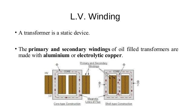
As the transformer has an lv winding overcurrent protection for this winding has been included as well. The main aim of transformer is to stepup or stepdown the voltage. Hv and lv windings are wound longitudinally along the core alternately. Winding of shell type transformer.
This configuration belongs to the vector group of transformer dyn1 where the lv lags the hv by 30. Mv lv transformers where everything starts the general term power supply in lv networks refers to the supply of electrical energy. So if you give some input on one of the windings you will receive output voltage on other side of windings. D for delta hv d for delta lv.
As shown the hv winding is connected in delta while the lv winding is connected in wye. Unless otherwise specified lv winding is always placed next to the core and hv winding over the lv winding in order to reduce the quantity of insulation used avoid the possibility of breakdown of the space between the core and hv coil in case hv coil is provided next to the core and to control the leakage reactance. The hv coils are sandwiched between two lv coils as shown in the figure below. The type of winding is given a letter again upper case for hv and lower case for lv windings for more detail please refer for the example below y for star hv y for star lv.
Typical ratios for hv mv transformers are. 132 33 145 11 132 11 115 34 5 and 115 13 2 kv.


